|
House
background
Heat Source
Controls
Loops
Information and Sources
Home
|
There are several reasons for doing this page.
I wanted to document this project as I have done on so many others.
I wanted to acknowledge all the information out there on radiant heat.
I wanted to possibly help someone considering a radiant project.
I wanted to prove that I could do it and it would work even on this "special" house.
In the beginning:
It is good to get an idea of the structure before getting into the details of the system. This is a post and beam frame house. As a friend said, it is basically a fancy barn. I know it is an old accepted method of building but it had challenges when installing under the floor radiant heat.
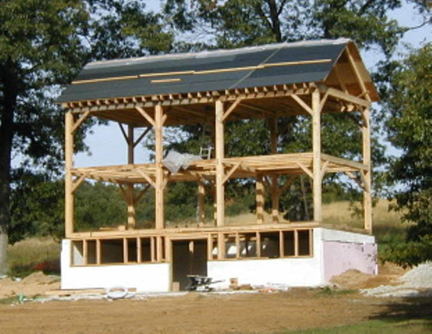
Under construction several years ago
Windows everywhere
There were two heat source problems from the beginning.
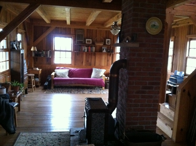
One was the attempt to heat with a
small wood burning stove on the first floor,
and second was to use a custom built masonry stove in the basement.
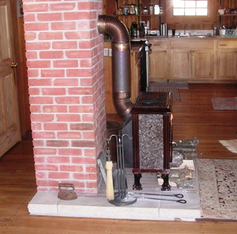
Small stove on first floor
Building and using masonry stoves is an old and accepted method of burning wood.
Check out the Masonry Heater Association of
North America
http://www.mha-net.org/
This one was not constructed properly and never functioned as intended.
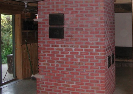
Side view in the basement.
The top of the masonry stove is actually the hearth on first floor.
My purpose here was to add a heat source that did not depend on wood.
Adding a larger first floor stove would make heating the house much easier.
Rebuilding or modifying the masonry stove
would be another option for better results. Even with both options there was still a need
for heat at times
when no one could load the wood.
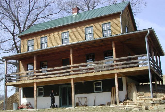
There are ten windows and two doors on the first
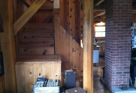
floor of this 18x36 house. It has a large stairwell that acts like a
chimney to the second floor. These are two other structural problems
that take heat away from the first floor regardless of heat source.
There are many opinions about radiant floor heat. Do a search and you can read forever about it.
Some of the reasons for deciding on it in this house listed below:
1. Forced air would mean duct work and cutting many holes in floor. Not an easy project with the masonry stove in center of the basement and oak beams everywhere. The other problem was that there is an oak beam on top of the foundation so a hole in the floor for registers would start about 10 inches out in the room. All the electrical outlets are on the floor out in the room. That is distasteful enough without having forced heat registers scattered out there also.
2. Having the heat source and control panel located in the selected corner would provide protection for water lines in severe cold. (last year when -21 the sink water line froze and olive oil became solid in cabinet.)
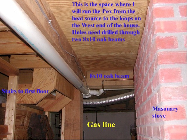
3. The hot water method would make the addition of solar panels and an outdoor wood burning boiler much easier since the delivery method would be in place with the Pex tubing already under the floor or running to radiators. This probably was the main consideration. If you want hot water solar you need a delivery system
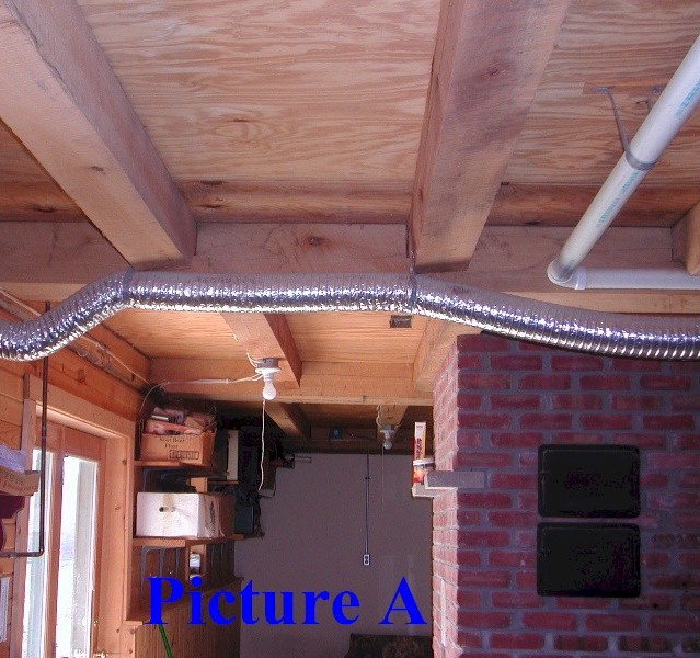
Not traditional floor joist:
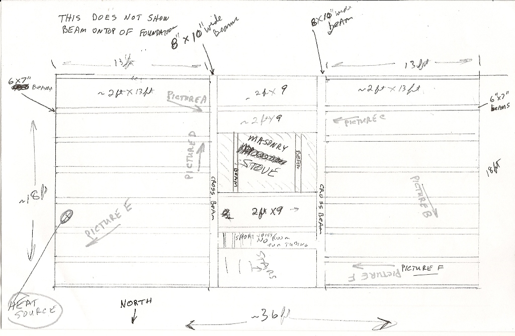
The pictures below show the beam construction. I made a sketch to submit to Nibco with the pictures as part of their marketing through Menards. "Normal" houses have floor joists on 16" centers so a layout usually corresponds to many plans you find for radiant floor heat. Having 6"x7" oak beams spaced 24" apart for joists is not a normal house.
The reply from Nibco was they only provide layouts on slab installations. That is not what the form says and I had already spent $900 on the RHP-1 panel and tubing so concluded I was on my own for the loop design.
Looking West past outside door and masonry
stove
Northwest corner of basement
Looking West again between outside door and
masonry stove
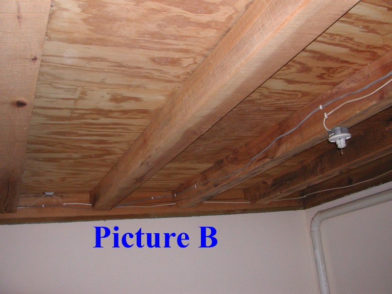
This shows the notches in the end of the 6x7 oak beams used as floor joists. These notches made installing the Pex under the floor radiant loops much easier. Without them each beam would have required holes drilled througth it.
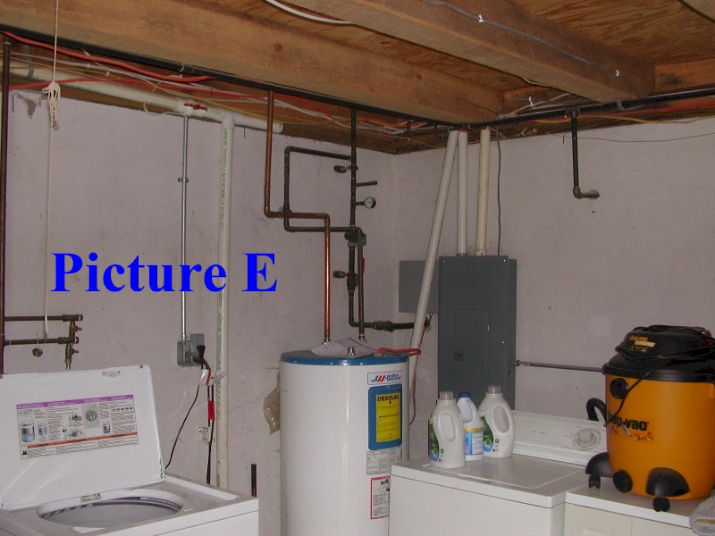
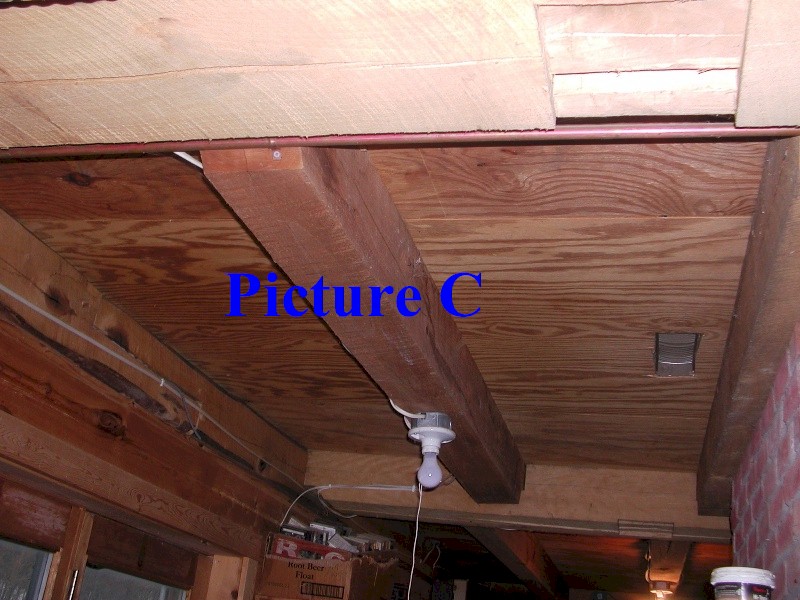
Notice the location of the electrical panel and the gas line
coming through foundation.
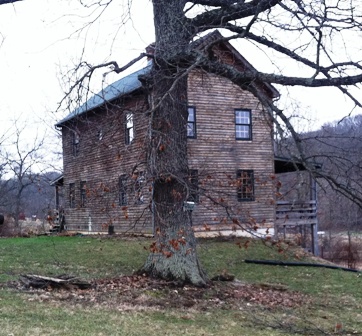
This will give a perspective of the project location.
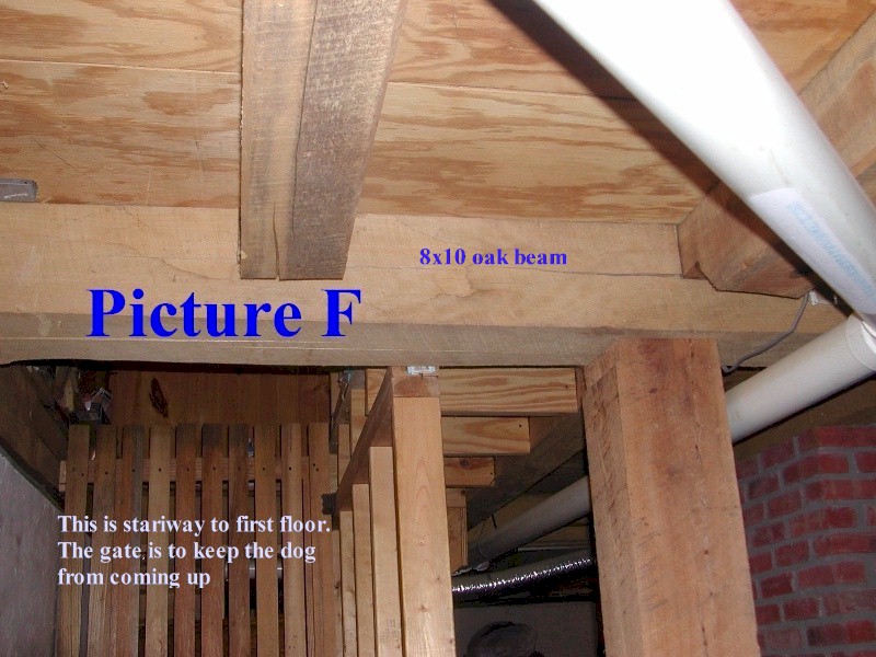
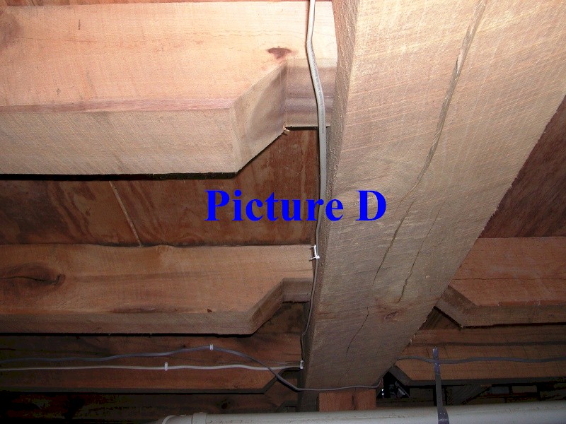
These last two pictures show the oak cross beam locations.
The picture below was taken when I stepped to the right of where Picture F was taken.
I am standing under the oak beam in Picture F
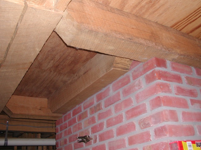
This shows the beams on sides of masonry stove
Next step: Installing the heat source
House background Heat Source Controls Loops Information and Sources